The lightning rod: how it works

The lightning rod, operating principle

Lightning strikes the fence or near it (a rare case, since the entire system is developed horizontally, there are no vertical metal parts). In general, the flow goes up the line arriving at the energizer trying to enter the grid. The flow arrives in front of the induction coil (n. 3), encounters resistance, and changes path.

It normally chooses to discharge into the soil (n. 1).

The parts that make up the recommended Lightning rod system are:

1
the 1.3 m long ground stake (Ref. T1) that you will drive into the ground directly under the tape near the gate post that houses the switch;
2
the lightning switch (Ref. 53) blocks the passage of current, lowering the golf ball like its counterpart (Ref. 52), but in addition it has a cable n. 4 which is fixed to the earth connection n. 1 and which attracts the lightning to the ground;
3
the Teflon cable (Ref. 28), rolled in ten coils, for about 10 m, creates an induction coil, which lengthens the path of the lightning and creates a magnetic field before the energizer. Finding this obstacle, the lightning that is looking for the shortest way to discharge to the ground usually changes its path, and discharges on the stake at point n. 1 with a small electric arc crossing n. 2 and cable n. 4;
4
the Teflon cable with a pointed terminal must be fixed with U-bolts to the fence post;
5
the energizer Ref. E5 installed under cover, near a power outlet, under a circuit breaker complying with standard safety laws;
6
Teflon connection cable to the earth connection (n. 7) which must be positioned near the energizer to be active against lightning, and then should be connected to the true earth which must be near the fence to optimize operation;
7
the earth stake, Ref. T1, connected to it must be as we said above, having an additional stake for electrical functions;
8
the current arrives from the energizer thanks to the Teflon cable Ref. 28 which connects to the switch of point n. 2 (Ref. 52) and from this it connects to the buckle of the tensioner Ref. 44V which blocks the tape;
9
use the lightning arrester Ref. 53A by applying it to some support screws of the part Ref. 44V. The lightning striking the fence will look for the shortest way to discharge to the ground passing through Ref. 53A.

N.B. We have observed that maximum functionality is achieved when, in a corner of the fence, a Ref. 44V is mounted as the upper insulator, and its two fixing screws are connected to a galvanized iron wire which is then discharged to the ground by means of a Ref. T1.
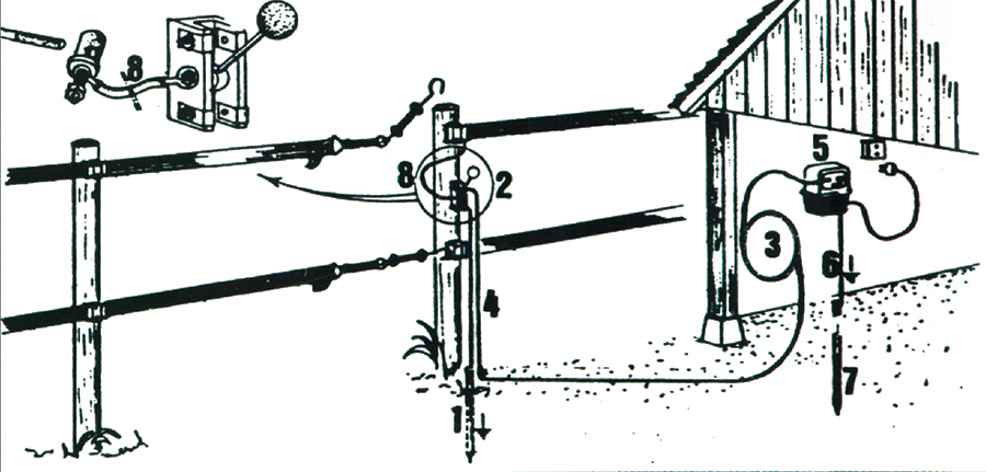
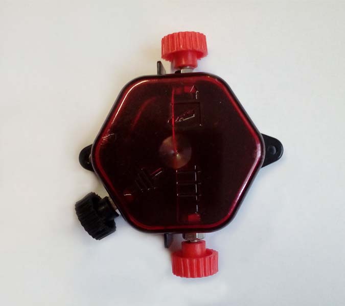
Lightning protection diagram 1 Lightning protection diagram 2

No products available yet

Stay tuned! More products will be shown here as they are added.